Selection guide Monitor and Processing
Preventa safety modules
|
Applications
|
|
Modules
|
For Emergency stop and switch monitoring
|
For Emergency stop
and protective guard
applications
|
For Emergency stop and switch monitoring
|
For Emergency stop, switch or solid-state output
safety light curtain monitoring
|
For Emergency stop,
switch, sensing mat/
edges or solid-state
output safety light
curtain monitoring
|
|
Maximum achievable safety level
|
PLe/Category 4
conforming
to EN/ISO 13849-1,
SILCL3 conforming
to EN/IEC 61508
and EN/IEC 62061
|
PLe/Category 4
conforming
to EN/ISO 13849-1,
SILCL3 conforming
to EN/IEC 61508
and EN/IEC 62061
|
PLe/Category 4
(instantaneous safety
outputs) and PLd/
Category 3 (time delay
safety
outputs) conforming to
EN/ISO 13849-1,
SILCL3 (instantaneous
safety outputs) and
SILCL2 (time delay
safety outputs)
conforming to
EN/IEC 61508
and EN/IEC 62061
|
PLe/Category 4
conforming to EN
ISO 13849-1,
SILCL3 conforming to
EN/IEC 62061
|
PLe/Category 4
conforming to
EN/ISO 13849-1,
SILCL3 conforming
to EN/IEC 61508
and EN/IEC 62061
|
PLe/Category 4
(instantaneous safety
outputs) and
PLd/Category 3 (time
delay safety outputs)
conforming to
EN/ISO 13849-1,
SILCL3 (instantaneous
safety outputs) and
SILCL2 (time delay
safety outputs)
conforming to
EN/IEC 61508
and EN/IEC 62061
|
PLe/Category 4
conforming to
EN/ISO 13849-1,
SILCL3 conforming
to EN/IEC 61508
and EN/IEC 62061
|
PLe/Category 4
conforming to
EN/ISO 13849-1,
SILCL3 conforming
to EN/IEC 61508
and EN/IEC 62061
|
PLe/Category 4
conforming to
EN/ISO 13849-1,
SILCL3 conforming
to EN/IEC 61508
and EN/IEC 62061
|
PLe/Category 4
conforming to
EN/ISO 13849-1,
SILCL3 conforming
to EN/IEC 61508
and EN/IEC 62061
|
|
Conformity to standards
|
EN/IEC 60204-1,
EN 1088/ISO 14119,
EN/ISO 13850,
EN/IEC 60947-1,
EN/IEC 60947-5-1
|
EN/IEC 60204-1,
EN 1088/ISO 14119,
EN/ISO 13850,
EN/IEC 60947-1,
EN/IEC 60947-5-1
|
EN/IEC 60204-1,
EN/ISO 13850,
EN 1088/ISO 14119,
EN/IEC 60947-1,
EN/IEC 60947-5-1
|
EN 62061
EN ISO 13849-1
EN 50156-1
EN 60204-1
EN/IEC 61496-1
EN/IEC 60947-5-1
|
EN/IEC 60204-1,
EN 1088/ISO 14119,
EN/ISO 13850,
EN/IEC 60947-1,
EN/IEC 60947-5-1
|
EN/IEC 60204-1,
EN/IEC 60947-1,
EN/IEC 60947-5-1,
EN/ISO 13850,
EN 1088/ISO 14119
|
EN/IEC 60204-1,
EN 1088/ISO 14119,
EN/ISO 13850,
EN/IEC 60947-1,
EN/IEC 60947-5-1
|
EN/IEC 60204-1,
EN 1088/ISO 14119,
EN/ISO 13850,
EN/IEC 60947-1,
EN/IEC 60947-5-1,
EN/IEC 61496-1 (type 4)
|
EN/IEC 60204-1,
EN 1088/ISO 14119,
EN/ISO 13850,
EN/IEC 60947-1,
EN/IEC 60947-5-1
|
EN/IEC 60204-1,
EN 1088/ISO 14119,
EN/ISO 13850,
EN/IEC 60947-1,
EN/IEC 60947-5-1
|
|
Product certifcations
|
UL, CSA, TÜV
|
UL, CSA, BG
|
UL, CSA, TÜV
|
UL, CSA, TÜV
|
UL, CSA, TÜV
|
UL, CSA, BG
|
UL, CSA, TÜV
|
UL, CSA, TÜV
|
UL, CSA, TÜV
|
UL, CSA, TÜV
|
|
Number of circuits
|
|
Safety
|
3 NO
|
3 NO
|
2 NO instantaneous
+ 3 NO time delay
|
3 NO instantaneous
+ 3 NO time delay
|
3 NO instantaneous
+ 3 NO time delay
|
2 NO instantaneous
+ 1 NO time delay
|
3 NO
|
7 NO
|
3 NO instantaneous
|
|
Additional
|
1 solid-state output
for signalling to PLC
|
1 relay output for
signalling
to PLC
|
4 solid-state outputs for
signalling to PLC
|
1 NC
|
3 solid-state outputs for
signalling to PLC
|
–
|
–
|
2 NC + 4 solid-state
outputs for signalling
to PLC
|
1 NC + 4 solid-state
outputs for signalling
to PLC
|
|
Display
|
2 LEDs
|
2 LEDs
|
4 LEDs
|
5 LEDs
|
11 LEDs
|
3 LEDs
|
3 LEDs
|
4 LEDs
|
4 LEDs
|
|
Supply voltage
|
a and 24 V c
48 V a
115 V a
230 V a
|
a and 24 V c
|
a and 24 V c
115 V a
230 V a
|
c 24 V
a 115…230 V
|
24 V c
|
24 V c
|
a and 24 V c
|
a and 24 V c
115 V a and 24 V c
230 V a and 24 V c
|
a and 24 V c
48 V a
110 V a and 24 V c
120 V a and 24 V c
230 V a and 24 V c
|
|
Synchronisation time between inputs
|
Unlimited
|
Unlimited
|
75 ms (automatic start)
|
1
|
Unlimited or 1.5 s
(depending on wiring)
|
Unlimited
|
Unlimited
|
Unlimited or 2 s, 4 s
(depending on wiring)
|
|
Input channel voltage
|
|
24 V/48 V version
|
a and 24 V c/48 V
a
|
24 V c
|
24 V c/–
|
24 V c/–
|
24 V c/–
|
24 V c/–
|
c 24 V/–
|
24 V c/–
|
24 V c/–
|
24 V/48 V or
110 V/120 V/230 V version
|
115 V a/230 V
–
|
–
|
48 V a/48 V
–
|
24 V c/–
|
–
–
|
––
|
––
|
24 V a/24 V
–
|
–
24 V c/24 V/24 V
|
|
Module type
|
XPSAC
|
XPSAXE
|
XPSATE
|
XPSATR
|
XPSAV
|
XPSABV
|
XPSAF
|
XPSAFL
|
XPSAR
|
XPSAK
|
|
Pages
|
3/74
|
3/74
|
3/75
|
3/76
|
3/75
|
3/75
|
3/77
|
3/78
|
3/79
|
3/80
|
9
1 2 3 4 5 6 7 8 9
10
1 2 3 4 5 6 7 8 9
10
3/69 3/69
Selection guide (continued) Monitor and Processing
Preventa safety modules
|
Applications
|
|
Modules
|
For enabling switch
monitoring
|
For electrical monitoring of two-hand control stations
|
For control of 1 to 4
single-beam photo-electric
sensors XU2 S (transmitter
receiver pair)
|
For monitoring type 2 and
type 4 light curtains
Compact and slim ranges
|
For extending the number of safety contacts
|
|
Maximum achievable safety level
|
PLe/Category 4 conforming to
EN/ISO 13849-1,
SILCL3 conforming to EN/
IEC 61508
and EN/IEC 62061
|
PLc/Category 1 conforming to
EN/ISO 13849-1
SILCL1 conforming to EN/IEC
62061
|
PLe/Category 4 conforming to
EN/ISO 13849-1,
SILCL3 conforming to
EN/IEC 61508
and EN/IEC 62061
|
PLe/Category 4 conforming to
EN/ISO 13849-1,
SILCL3 conforming to
EN/IEC 61508
and EN/IEC 62061
|
PLc/Category 2 conforming to
EN/ISO 13849-1,
SILCL1 conforming to
EN/IEC 61508
and EN/IEC 62061
|
PLe/Category 4 conforming to
EN/ISO 13849-1,
SILCL3 conforming to
EN/IEC 61508
and EN/IEC 62061
|
PLe/Category 4 conforming
to EN/ISO 13849-1,
SILCL3 conforming to
EN/IEC 61508
and EN/IEC 62061 (when
connected to the appropriate
module)
|
PLe/Category 4 conforming to
EN/ISO 13849-1, SILCL3
conforming
to EN/IEC 61508
and EN/IEC 62061 (when
connected to the appropriate
module)
|
|
Conformity to standards
|
EN/IEC 60204-1,
EN 61326,
EN/IEC 60947-1,
EN/IEC 60947-5-1
|
EN 574 type III A,
EN/IEC 60204-1,
EN/IEC 60947-5-1,
EN 62061
|
EN/IEC 60204-1,
EN/IEC 60947-1,
EN/IEC 60947-5-1,
EN 574 type III C/ISO 13851
|
EN/IEC 60204-1,
EN/IEC 60947-1,
EN/IEC 60947-5-1,
EN 574 type III C/ISO 13851
|
EN/IEC 61496-1,
EN/IEC 61496-2,
EN/IEC 60204-1,
EN/IEC 60947-1,
EN/IEC 60947-5-1
|
EN/IEC 61496-1,
EN/IEC 61496-2,
EN/IEC 60204-1,
EN/IEC 60947-1,
EN/IEC 60947-5-1
|
EN/IEC 60204-1,
EN/IEC 60947-1,
EN/IEC 60947-5-1
|
EN/IEC 60204-1,
EN/IEC 60947-1,
EN/IEC 60947-5-1
|
|
Product certifcations
|
UL, CSA, TÜV
|
UL, CSA, TÜV
|
UL, CSA, BG
|
UL, CSA, TÜV
|
UL, CSA, IFA
|
UL, CSA, TÜV
|
UL, CSA, BG
|
UL, CSA, TÜV
|
|
Number of circuits
|
|
Safety
|
2 NO
|
1 NO
|
2 NO
|
2 NO
|
2 NO
|
2 solid-state
|
4 NO
|
8 NO
|
|
Additional
|
2 solid-state outputs for
signalling to PLC
|
1 NC
|
1 NC
|
2 solid-state outputs for
signalling to PLC
|
4 solid-state PNP NO outputs
for signalling to PLC
|
1 PNP + 1 NPN output for
signalling to PLC
|
2 NC
|
1 NC
|
|
Display
|
3 LEDs
|
2 LEDs
|
3 LEDs
|
3 LEDs
|
4 LEDs
|
14 LEDs + 2-digit display
|
2 LEDs
|
3 LEDs
|
|
Supply voltage
|
24 V c
|
a and 24 V c
115/230 V a
|
a and 24 V c
115/120 V a
230 V a
|
24 V c
|
24 V c
|
24 V c
|
a and 24 V c
|
a and 24 V c
115 V a
230 V a
|
|
Synchronisation time between inputs
|
–
|
500 ms
|
500 ms
|
500 ms
|
–
|
3 s or infnite
|
–
|
–
|
|
Input channel voltage
|
|
24 V/48 V version
|
24 V/–
|
24 V c/–
|
24 V c
|
24 V c/–
|
–
|
–
|
–
|
–
|
|
115 V/230 V version
|
–
|
24 V a/24 V
|
–
|
–
|
–
|
–
|
–
|
–
|
|
Module type
|
XPSVC
|
XPSBAE
|
XPSBCE
|
XPSBF
|
XPSCM
|
XPSLCM
|
XPSECME
|
XPSECPE
|
|
Pages
|
3/81
|
3/82
|
3/82
|
3/82
|
3/83
|
3/84
|
3/85
|
3/85
|
70 3/71
1 2 3 4 5 6 7 8 9
10
1 2 3 4 5 6 7 8 9
10
3/70 3/70
Selection guide (continued) Monitor and Processing
Preventa safety modules
|
Applications
|
|
Modules
|
For the monitoring of applications
requiring safety time delays
|
For coded magnetic switch monitoring
|
For zero speed detection of
AC or DC motors which
produce a remanent voltage
in their windings due to
residual magnetism
|
For lift control
|
For dynamic monitoring of
hydraulic valves on linear
presses
|
For dynamic monitoring of
double-bodied solenoid
valves
|
For safety stop at top dead
centre with automatic
overtravel monitoring and
control
|
|
For 2 max.
|
For 6 max.
|
|
Maximum achievable safety level
|
PL d/Category 3
conforming
to EN/ISO 13849-1,
SILCL 2 conforming to
EN/IEC 62061
|
PL d/Category 3
conforming
to EN/ISO 13849-1,
SILCL 2 conforming to
EN/IEC 62061
|
PL e/Category 4
conforming
to EN/ISO 13849-1
SILCL 3 conforming to
EN/IEC 62061
|
PL e/Category 4
conforming
to EN/ISO 13849-1
SILCL 3 conforming to
EN/IEC 62061
|
PL d/Category 3 conforming
to EN/ISO 13849-1,
SILCL 2 conforming to EN/
IEC 62061,
|
PL e/Category 4 conforming
to EN/ISO 13849-1,
SILCL 3 conforming to EN/
IEC 62061
|
PL e/Category 4 conforming to
EN/ISO 13849-1,
SILCL 3 conforming to EN/
IEC 62061
|
PL e/Category 4 conforming
to EN/ISO 13849-1,
SILCL 3 conforming to EN/
IEC 62061
|
PL e/Category 4 conforming
to EN/ISO 13849-1,
SILCL 3 conforming to EN/
IEC 62061
|
|
Conformity to standards
|
EN/IEC 60204-1,
EN/IEC 60947-1,
EN/IEC 60947-5-1
|
EN/IEC 60204-1,
EN/IEC 60947-1,
EN/IEC 60947-5-1
|
EN/IEC 60204-1,
EN 1088/ISO 14119,
EN/IEC 60947-1,
EN/IEC 60947-5-1,
EN/IEC 60947-5-3
|
EN/IEC 60204-1,
EN 1088/ISO 14119,
EN/IEC 60947-1,
EN/IEC 60947-5-1,
EN/IEC 60947-5-3
|
EN/IEC 60204-1,
EN/IEC 60947-1,
EN/IEC 60947-5-1
|
EN 81-1,
EN 81-2,
EN/IEC 60947-5-1,
EN 12015,
EN 12016
|
EN 693,
EN/IEC 60204-1,
EN/IEC 60947-1,
EN/IEC 60947-5-1
|
EN 692,
EN/IEC 60204-1,
EN/IEC 60947-1,
EN/IEC 60947-5-1
|
EN 692,
EN/IEC 60204-1,
EN/IEC 60947-1,
EN/IEC 60947-5-1
|
|
Product certifcations
|
UL, CSA, TÜV
|
UL, CSA, TÜV
|
UL, CSA, TÜV
|
UL, CSA, TÜV
|
UL, CSA, TÜV
|
TÜV
|
UL, CSA, TÜV
|
UL, CSA, TÜV
|
UL, CSA, TÜV
|
|
Number of circuits
|
|
Safety
|
1 NO time delayed
|
1 NO pulse type
|
2 NO
|
1 NO + 1 NC
|
2 NO
|
2 NO + 1 NC
|
1 NO + 1 NC
|
3 NO
|
|
Additional
|
2 NC + 2 solid-state outputs for signalling to
PLC
|
2 solid-state outputs for signalling to PLC
|
2 solid-state outputs for signalling to PLC
|
–
|
4 solid-state outputs for signalling to PLC
|
|
Display
|
4 LEDs
|
3 LEDs
|
15 LEDs
|
4 LEDs
|
4 LEDs
|
8 LEDs
|
|
Supply voltage
|
a and 24 V c
115 V a
230 V a
|
c 24 V
|
24 V c
115 V a
230 V a
|
a and 24 V c
|
24 V c
|
24 V c
115 V a
230 V a
|
–
115 V a
230 V a
|
|
Synchronisation time between inputs
|
–
|
–
|
500 ms
|
–
|
Infnite
|
–
|
–
|
–
|
|
Module type
|
XPSTSA
|
XPSTSW
|
XPSDMB
|
XPSDME
|
XPSVNE
|
XPSEDA
|
XPSPVT
|
XPSPVK
|
XPSOT
|
|
Pages
|
3/86
|
3/86
|
3/87
|
3/87
|
3/88
|
3/89
|
3/90
|
3/91
|
3/93
|
3/72 3/73
3/74
Operating principle,
references
Monitor and Processing
Preventa safety modules types XPSAC,
XPSAXE
For Emergency stop and switch monitoring
|
Operating principle
|
Safety modules XPSAC and XPSAXE are used for monitoring Emergency stop
circuits conforming to standards EN/ISO 13850 and EN/IEC 60204-1 and also
meet the safety requirements for the electrical monitoring of switches in protective
devices conforming to standard EN/ISO 14119. They provide protection for both the
machine operator and the machine by immediately stopping the dangerous
movement on receipt of a stop instruction from the operator, or on detection of a
fault in the safety circuit itself.
To aid diagnostics, the modules have LEDs which provide information on the
monitoring circuit status.
b The XPSAC module has 3 safety outputs and a solid-state output for signalling to
the PLC.
b The XPSAXE module has 3 safety outputs and a relay output for signalling to the
PLC
|
|
References
|
|
Description
|
Connection
|
Number of
instantaneous
opening
safety circuits
|
Additional
outputs
|
Supply
|
Reference
|
Weight
kg/
lb
|
Safety modules for
Emergency stop and switch
monitoring
|
Captive screw
clamp terminals
Terminal block
integrated
in module
|
3
|
1 solid-state
|
a and c 24 V
|
XPSAC5121
|
0.160/
0.353
|
|
a 48 V
|
XPSAC1321
|
0.210/
0.463
|
|
a 115 V
|
XPSAC3421
|
0.210/
0.463
|
|
a 230 V
|
XPSAC3721
|
0.210/
0.463
|
Captive screw clamp
terminals
Terminal block
removable from
module
|
3
|
1 solid-state
|
a and
c 24 V
|
XPSAC5121P
|
0.160/
0.353
|
|
a 48 V
|
XPSAC1321P
|
0.210/
0.463
|
|
a 115 V
|
XPSAC3421P
|
0.210/
0.463
|
|
a 230 V
|
XPSAC3721P
|
0.210/
0.463
|
|
1 relay
|
a and
c 24 V
|
XPSAXE5120P
|
0.229/
0.505
|
Spring terminals
Terminal block
removable from
module
|
3
|
1 relay
|
a and
c 24 V
|
XPSAXE5120C
|
0.229/
0.505
|
XPSAXE5120P
XPSAXE5120C
XPSAC ppppP
XPSAC pppp
1 2 3 4 5 6 7 8 9
10
3/75
Operating principle,
references
Monitor and Processing
Preventa safety modules types XPSAV,
XPSABV, XPSATE
For Emergency stop and switch monitoring
|
Operating principle
|
Safety modules XPSAV, XPSABV and XPSATE are used for monitoring Emergency stop circuits conforming
to standards EN/ISO 13850 and EN/IEC 60204-1 and also meet the safety requirements for the electrical
monitoring
of switches in protection devices conforming to standard EN/ISO 14119.
They provide protective for both the machine operator and the machine by immediately stopping the dangerous
movement on receipt of a stop instruction from the operator, or on detection of a fault in the safety circuit itself.
In addition to the stop category 0 instantaneous opening safety outputs (3 for XPSAV, 2 for XPSABV and 2 for
XPSATE), the modules incorporate stop category 1 time delay outputs (3 for XPSAV, 1 for XPSABV and 3 for
XPSATE) which allow for controlled deceleration of the motor components until a complete stop is achieved (for
example, motor braking by variable speed drive).
At the end of the preset delay, the supply is disconnected by opening the time delay output circuits.
b For module XPSAV, the time delay of the 3 output circuits is adjustable, in 15 preset values, between 0 and 300
seconds using selector buttons.
b For module XPSABV, the time delay of the 3 output circuits is adjustable between 0.15 and 3 seconds or 1.5
and 30 seconds, depending on the model, using a selector switch.
b For module XPSATE, the time delay of the 3 output circuits is adjustable between 0 and 30 seconds using a
12-position selector switch.
Module XPSAV also incorporates 3 solid-state signalling outputs for signalling to the process PLC.
Module XPSATE incorporates 4 solid-state signalling outputs for signalling to the process PLC.
To aid diagnostics, the modules have LEDs which provide information on the monitoring circuit status.
The Start button monitoring function is confgurable depending on the wiring.
|
|
References
|
|
Description
|
Connection
|
Number of
safety circuits
|
Additional
outputs
|
Setting range
of time delay
|
Supply
|
Reference
|
Weight
kg/
lb
|
Safety
modules for
Emergency
stop and
switch
monitoring
|
Captive screw clamp
terminals
Terminal block
integrated in module
|
6 NO
(3 NO time delay)
|
3 solid-state
|
0…300 s
|
c 24 V
|
XPSAV11113
|
0.320/
0.705
|
Captive screw clamp
terminals
Terminal block
removable from module
|
6 NO
(3 NO time delay)
|
3 solid-state
|
0…300 s
|
c 24 V
|
XPSAV11113P
|
0.320/
0.705
|
Captive screw clamp
terminals
Terminal block
integrated in module
|
6 NO
(3 NO time delay)
|
3 solid-state
|
0…300 s
(Start delay 0,5 s)
|
c 24 V
|
XPSAV11113T050
|
0.320/
0.705
|
6 NO
(3 NO time delay)
|
3 solid-state
|
0.1 …2 s
|
c 24 V
|
XPSAV11113Z002
|
0.320/
0.705
|
3 NO
(1 NO time delay)
|
–
|
0,15…3 s
|
c 24 V
|
XPSABV1133P
|
0.280/
0.617
|
Captive screw clamp
terminals
Terminal block
removable from module
|
Spring terminals
Terminal block
removable from module
|
3 NO
(1 NO time delay)
|
–
|
0,15…3 s
|
c 24 V
|
XPSABV1133C
|
0.275/
0.606
|
Captive screw clamp
terminals
Terminal block
removable from module
|
3 NO
(1 NO time delay)
|
–
|
1,5…30 s
|
c 24 V
|
XPSABV11330P
|
0.280/
0.617
|
Spring terminals
Terminal block
removable from module
|
3 NO
(1 NO time delay)
|
–
|
1,5…30 s
|
c 24 V
|
XPSABV11330C
|
0.275/
0.606
|
Captive screw clamp
terminals
Terminal block
integrated in module
|
5 NO
(3 NO time delay)
|
4 solid-state
|
0…30 s
|
a and
c 24 V
|
XPSATE5110
|
0.280/
0.617
|
Captive screw clamp
terminals
Terminal block
removable from module
|
5 NO
(3 NO time delay)
|
4 solid-state
|
0…30 s
|
a and
c 24 V
|
XPSATE5110P
|
0.280/
0.617
|
Captive screw clamp
terminals
Terminal block
integrated in module
|
5 NO
(3 NO time delay)
|
4 solid-state
|
0…30 s
|
a 115 V
|
XPSATE3410
|
0.380/
0.838
|
Captive screw clamp
terminals
Terminal block
removable from module
|
5 NO
(3 NO time delay)
|
4 solid-state
|
0…30 s
|
a 115 V
|
XPSATE3410P
|
0.380/
0.838
|
Captive screw clamp
terminals
Terminal block
integrated in module
|
5 NO
(3 NO time delay)
|
4 solid-state
|
0…30 s
|
a 230 V
|
XPSATE3710
|
0.380/
0.838
|
Captive screw clamp
terminals
Terminal block
removable from module
|
5 NO
(3 NO time delay)
|
4 solid-state
|
0…30 s
|
a 230 V
|
XPSATE3710P
|
0.380/
0.838
|
XPSABV ppppP
XPSABV ppppC
XPSAV11113
XPSAV11113P
XPSATE5110
1 2 3 4 5 6 7 8 9
10
3/76
Operating principle,
references
Monitor and Processing
Preventa safety module type XPSATR
For Emergency stop and protective guard applications
|
Operating principle
|
Safety modules XPSATR meet the requirements of Performance Level PL e/Category 4
conforming to standard EN ISO 13849-1.
Safety modules XPSATR are electronic, redundant and self-monitoring devices with
positively driven relays.
They are used for monitoring Emergency stop circuits (single or two-channel) and
protective guard applications.
The modules are conforming to standards EN/ISO 13850 and EN 60204-1.
They provide protection for both the machine operator and the machine by
immediately stopping the dangerous movement on receipt of a stop instruction from
the operator, or on detection of a fault in the safety circuit itself.
XPSATR incorporate 3 NO and 1 NC not delayed contacts and 3 delayed NO
contacts.
To aid diagnostics, the modules have 5 LEDs on the front face which provide
information on the monitoring circuit status.
|
|
References
|
|
Description
|
Connection
|
Number of
safety circuits
|
Additional
outputs
|
Time
setting
range
|
Supply
|
Reference
|
Weight
kg/
lb
|
Safety
modules for
emergency
stop
and safety
guards
monitoring
|
Captive screw
clamp terminals
Terminal block
removable from
module
|
3 NO
+ 3 NO time delay
|
1 NC
|
0.1…3 s
|
c 24 V
|
XPSATR1153P
|
0.330/
0.728
|
|
0.1…3 s
|
a 115…230 V
|
XPSATR3953P
|
0.350/
0.772
|
|
0…30 s
|
c 24 V
|
XPSATR11530P
|
0.330/
0.728
|
|
0…30 s
|
a 115…230 V
|
XPSATR39530P
|
0.350/
0.772
|
Cage clamp
terminals
Terminal block
removable from
module
|
3 NO
+ 3 NO time delay
|
1 NC
|
0.1…3 s
|
c 24 V
|
XPSATR1153C
|
0.330/
0.728
|
|
0.1…3 s
|
a 115…230 V
|
XPSATR3953C
|
0.350/
0.772
|
|
0…30 s
|
c 24 V
|
XPSATR11530C
|
0.330/
0.728
|
|
0…30 s
|
a 115…230 V
|
XPSATR39530C
|
0.350/
0.772
|
XPSATR ppppP
XPSATR ppppC
1 2 3 4 5 6 7 8 9
10
3/77
Operating principle,
references
Monitor and Processing
Preventa safety modules type XPSAF
For Emergency stop and switch monitoring
|
Operating principle
|
Safety modules XPSAF meet the requirements of Performance Level PL e/Category 4
conforming to standard EN/ISO 13849-1.
They are used for:
b Monitoring Emergency stop circuits conforming to standards EN/ISO 13850 and
EN/IEC 60204-1.
b Electrical monitoring of switches activated by protection devices conforming
to standard EN/ISO 14119.
Housed in a compact enclosure, the modules have 3 safety outputs.
Preventa safety modules XPSAFppppP incorporate removable terminal blocks, thus
optimising machine maintenance.
To aid diagnostics, the modules have 3 LEDs on the front face which provide
information on the monitoring circuit status.
The Start button monitoring function is confgurable depending on the wiring.
|
|
References
|
|
Description
|
Connection
|
Number of safety
circuits
|
Supply
|
Reference
|
Weight
kg/
lb
|
Safety modules for
Emergency stop and switch
monitoring
|
Captive screw clamp terminals
Terminal block integrated
in module
|
3
|
a and
c 24 V
|
XPSAF5130
|
0.250/
0.551
|
Captive screw clamp terminals
Terminal block removable from
module
|
3
|
a and
c 24 V
|
XPSAF5130P
|
0.250/
0.551
|
XPSAF5130
1 2 3 4 5 6 7 8 9
10
3/78
Operating principle,
references
Monitor and Processing
Preventa safety modules type XPSAFL
For Emergency stop, switch and safety light curtain
monitoring
|
Operating principle
|
Safety modules XPSAFL meet the requirements of Performance Level
PL e/Category 4 conforming to standard EN/ISO 13849-1.
They are used for:
b Monitoring Emergency stop circuits conforming to standards EN/ISO 13850 and
EN/IEC 60204-1.
b Electrical monitoring of switches activated by protection devices conforming to
standard EN/ISO 14119.
They can also be used for monitoring type 4 light curtains conforming to EN 61496-1
that have solid-state safety outputs (for example, light curtains type XUS L, see
page 30304-EN/2). This system conforms to Performance Level PL e/Category 4 in
accordance with EN/ISO 13849-1.
Housed in a compact enclosure, the modules have 3 safety outputs.
Preventa safety modules XPSAFLppppP incorporate removable terminal blocks,
thus optimising machine maintenance.
To aid diagnostics, the modules have 3 LEDs on the front face which provide
information on the monitoring circuit status.
The Start button monitoring function is confgurable depending on the wiring.
|
|
References
|
|
Description
|
Connection
|
Number of
safety circuits
|
Supply
|
Reference
|
Weight
kg/
lb
|
Safety modules for
Emergency stop,
switch and safety light curtain
monitoring
|
Captive screw clamp terminals
Terminal block integrated in module
|
3
|
a and
c 24 V
|
XPSAFL5130
|
0.250/
0.551
|
Captive screw clamp terminals
Terminal block removable from
module
|
3
|
a and
c 24 V
|
XPSAFL5130P
|
0.250/
0.551
|
XPSAFL5130
1 2 3 4 5 6 7 8 9
10
3/79
Operating principle,
references
Monitor and Processing
Preventa safety modules type XPSAR
For Emergency stop, switch or safety light curtain
monitoring
|
Operating principle
|
Safety modules XPSAR meet the requirements of Performance Level PL e/
Category 4 conforming to standard EN/ISO 13849-1 and are designed for the
following safety applications:
b Monitoring Emergency stop circuits conforming to EN/ISO 13850 and
EN/IEC 60204-1.
b Electrical monitoring of switches activated by protection devices conforming
to standard EN/ISO 14119.
b Monitoring type 4 light curtains conforming to EN/IEC 61496-1 that have
solid-state safety outputs with test function (light curtains XUS L).
In addition to 7 safety outputs, modules XPSAR incorporate 2 relay signalling
outputs and 4 solid-state signalling outputs for signalling to the process PLC.
Safety modules XPSARppppppP incorporate removable terminal blocks, thus
optimising machine maintenance.
To aid diagnostics, the modules have 4 LEDs on the front face which provide
information on the monitoring circuit status.
The Start button monitoring function is confgurable depending on the wiring.
|
|
References
|
|
Description
|
Connection
|
Number
of
safety circuits
|
Additional
outputs/
solid-state
outputs to PLC
|
Supply
|
Reference
|
Weight
kg/
lb
|
Safety modules for
Emergency stop, switch
or safety light curtain
monitoring
|
Captive screw
clamp
terminals,
Terminal block
integrated
in module
|
7
|
2 / 4
|
a and c 24 V
|
XPSAR311144
|
0.300/
0.661
|
a 115 V
c 24 V
|
XPSAR351144
|
0.400/
0.882
|
a 230 V
c 24 V
|
XPSAR371144
|
0.400/
0.882
|
Captive screw
clamp
terminals,
Terminal block
removable from
module
|
7
|
2 / 4
|
a and c 24 V
|
XPSAR311144P
|
0.300/
0.661
|
a 115 V
c 24 V
|
XPSAR351144P
|
0.400/
0.882
|
a 230 V
c 24 V
|
XPSAR371144P
|
0.400/
0.882
|
XPSAR3 p1144
1 2 3 4 5 6 7 8 9
10
3/80
Operating principle,
references
Monitor and Processing
Preventa safety modules type XPSAK
For Emergency stop, switch, sensing mat/edges
or safety light curtain monitoring
|
Operating principle
|
Safety modules XPSAK meet the requirements of Performance Level PL e/Category 4
conforming to standard EN/ISO 13849-1.
They are used for:
b Monitoring Emergency stop circuits conforming to standards EN/ISO 13850 and
EN/IEC 60204-1.
b Electrical monitoring of switches activated by protection devices, with optional
selection of synchronisation time between signals.
b Monitoring 4-wire sensing mats or edges.
b Monitoring type 4 light curtains conforming to EN/IEC 61496-1 which have
solid-state safety outputs with test function (light curtains XUSL).
Housed in a compact enclosure, the modules have 3 safety outputs, a relay signalling
output and 4 solid-state signalling outputs for signalling to the process PLC.
Preventa safety modules XPSAKppppP incorporate removable terminal blocks,
thus optimising machine maintenance.
To aid diagnostics, the modules have 4 LEDs on the front face which provide
information on the monitoring circuit status.
The Start button monitoring function is confgurable depending on the wiring.
|
|
References
|
|
Description
|
Connection
|
Number
of safety
circuits
|
Additional
outputs /
Solid-state
outputs for PLC
|
Supply
|
Reference
|
Weight
kg/
lb
|
Safety modules for
Emergency stop, switch,
sensing mat/edges or safety
light curtain monitoring
|
Captive screw
clamp terminals
Terminal block
integrated in
module
|
3
|
1 / 4
|
a and
c 24 V
|
XPSAK311144
|
0.300/
0.661
|
a 110 V
c 24 V
|
XPSAK361144
|
0.400/
0.882
|
a 120 V
c 24 V
|
XPSAK351144
|
0.400/
0.882
|
a 230 V
c 24 V
|
XPSAK371144
|
0.400/
0.882
|
Captive screw
clamp terminals
Terminal block
removable from
module
|
3
|
1 / 4
|
a and
c 24 V
|
XPSAK311144P
|
0.300/
0.661
|
|
a 48 V
|
XPSAK331144P
|
0.300/
0.661
|
a 110 V
c 24 V
|
XPSAK361144P
|
0.400/
0.882
|
a 120 V
c 24 V
|
XPSAK351144P
|
0.400/
0.882
|
a 230 V
c 24 V
|
XPSAK371144P
|
0.400/
0.882
|
XPSAK3 p1144
1 2 3 4 5 6 7 8 9
10
3/81
Operating principle,
references
Monitor and Processing
Preventa safety modules type XPSVC
For enabling switch monitoring
|
Operating principle
|
The enabling grip switch system, comprising an enabling switch XY2AU and a monitoring
module XPSVC, enables authorised personnel to carry out adjustment, programming
or maintenance operations within hazardous zones of machines providing certain
conditions are met.
To be accessible, such operations are often carried out at reduced speed, and must
be intentionally selected by authorised persons by means of a selector switch or key
switch. Once the selection is made, the enabling switch system temporarily takes over
from the hazardous zone’s usual protection measures.
Caution: The enabling switch system alone must not cause dangerous movements of
the machine to be activated; a second intentional control action on the part of the
operator is required. In addition, each person remaining in the hazardous zone must
be provided with an individual enabling switch to ensure their own safety.
|
|
References
|
|
Description
|
Connection
|
Number of
safety circuits
|
Solid-state
outputs for PLC
|
Supply
|
Reference
|
Weight
kg/
lb
|
Safety modules for enabling
switch monitoring
|
Captive screw
clamp terminals
Terminal block
integrated in
module
|
2 NO
|
2
|
c 24
|
XPSVC1132
|
0.250/
0.551
|
Captive screw
clamp terminals
Terminal block
removable from
module
|
2 NO
|
2
|
c 24
|
XPSVC1132P
|
0.250/
0.551
|
XPSVC1132
1 2 3 4 5 6 7 8 9
10
3/82
|
Operating principle
|
Two-hand control stations are designed to provide protection against hand injury.
They require machine operators to keep their hands clear of the dangerous movement zone.
The use of two-hand control is an individual protective measure, which can safely protect only one operator.
Separate two-hand control stations must be provided for each operator in a multiple-worker environment.
Safety modules XPSBAE, BCE and BF for two-hand control stations comply with the requirements of European
standard EN 574/ISO 13851 for two-hand control systems.
The control stations must be designed and installed such that they cannot be activated involuntarily or easily
rendered inoperative. Depending on the application, the requirements of type C standards specifc to the
machinery involved must be met (additional personal protection methods may have to be considered).
To initiate a dangerous movement, both operators (two-hand control pushbuttons) must be activated within an
interval y 0.5 s (synchronous activation). If one of the two pushbuttons is released during a dangerous operation,
the control sequence is cancelled. Resumption of the dangerous operation is possible only if both pushbuttons
are returned to their initial position and reactivated within the required time interval.
The safety distance between the control units and the hazardous zone must be suffcient to ensure that when only
one operator is released, the hazardous zone cannot be reached before the dangerous movement has been
completed or stopped.
|
|
Selection
|
|
Requirements of standard EN 574/ISO 13851
|
Type I
|
Type II
|
Type III
|
|
A
|
B
|
C
|
Standard EN 574/
ISO 13851 defnes the
selection of two-hand
controls according to its
behavior.
The following table details
the 3 types of two-hand
control conforming to EN
574/ISO 13851.
For each type, it lists the
operating characteristics
and minimum requirements.
|
Use of both hands (simultaneous action)
|
|
Link between input and output signals
|
|
Output signal inhibited
|
|
Prevention of accidental operation
|
|
Tamper-proof
|
|
Output signal reinitialised
|
|
Synchronous action (specifed time limit)
|
Use of proven components
(Category 1 conforming to EN/ISO 13849-1)
|
XPSBAE
|
Redundancy with partial error detection
(Category 3 conforming to EN/ISO 13849-1)
|
XPSBCE
XPSBF
|
Redundancy + Self-monitoring
(Category 4 conforming to EN/ISO 13849-1)
|
XPSBCE
XPSBF
|
|
Two-hand control station
|
XY2SBpp
|
|
Conforming to standard EN/ISO 13849-1
|
Meets the requirements of standard EN
574/ISO 13851
|
|
References
|
|
Description
|
Type
conforming
to standard
EN 574
|
Connection
|
Number of
safety
circuits
|
Additional
outputs
|
Supply
|
Reference
|
Weight
kg/
lb
|
Safety
modules for
electrical
monitoring
of two-hand
control
stations
|
III A
|
Captive screw clamp
terminals
Terminal block
removable from
module
|
1 NO
|
1 NC
|
a and 24 V c
|
XPSBAE5120P
|
0.100/
0.220
|
|
a 115/230V
|
XPSBAE3920P
|
0.100/
0.220
|
Spring terminals
Terminal block
removable from
module
|
1 NO
|
1 NC
|
a and 24 V c
|
XPSBAE5120C
|
0.100/
0.220
|
|
a 115/230V
|
XPSBAE3920C
|
0.100/
0.220
|
|
III C
|
Captive screw clamp
terminals
Terminal block
removable from
module
|
2 NO
|
1 NC relay
|
a and 24 V c
|
XPSBCE3110P
|
0.272/
0.600
|
|
a 115/120 V
|
XPSBCE3410P
|
0.322/
0.710
|
|
a 230 V
|
XPSBCE3710P
|
0.322/
0.710
|
Spring terminals
Terminal block
removable from
module
|
2 NO
|
1 NC relay
|
a and 24 V c
|
XPSBCE3110C
|
0.272/
0.600
|
|
a 115 /120 V
|
XPSBCE3410C
|
0.322/
0.710
|
|
a 230 V
|
XPSBCE3710C
|
0.322/
0.710
|
Captive screw clamp
terminals
Terminal block
removable from
module
|
2 NO
|
2 solid-state
|
c 24 V
|
XPSBF1132
|
0.150/
0.331
|
|
2 NO
|
2 solid-state
|
c 24 V
|
XPSBF1132P
|
0.150/
0.331
|
Operating principle,
selection,
references
Monitor and Processing
Preventa safety modules types XPSBAE,
XPSBCE, XPSBF
For electrical monitoring of two-hand control stations
XPSBCE ppppP
XPSBCE ppppC
XPSBF1132
XPSBAE ppppP
XPSBAE ppppC
1 2 3 4 5 6 7 8 9
10
3/83
|
Operating principle
|
XPSCM safety modules used in conjunction with XU2S single-beam photo-electric
sensors (periodically tested), establish a category 2 light curtain conforming
to IEC/EN 61496 parts 1 and 2.
The connection of 1 to 4 pairs of XU2S photo-electric sensors makes it possible
to create a protected zone up to 1200 mm high conforming to EN 999/ISO 13855
and 8 m long.
The built-in “muting” function allows the automatic passage of parts to be machined,
or loaded pallets, without interrupting the transportation movement.
When the system is switched on by the start command (in series with the main circuit
feedback loop) and the light protection is not interrupted, the main circuit is closed
by the two safety relays of the XPSCM module.
An interruption of the protective feld causes the safety outputs to open instantaneously,
and the process PLC receives a stop command. The LED on the XPSCM front panel
changes from green to red. The “open” state is maintained until the module is restarted
using the start button.
The “muting” function allows the light curtain protection to be inhibited. This can be
used to authorise the passage of a materials trolley through the light curtain without
tripping the main circuit. The “muting” function cannot be activated by supplying the
inhibition sensors unless the safety outputs have been switched on beforehand.
To trigger the “muting” function, the inhibition devices must be activated within the
3 second time interval. This synchronisation time for the two inhibition inputs can be
deactivated by connecting two confguration terminals. The “muting” cycle has a maximum
duration of 60 seconds. During this period, materials can be transported through the
protection feld without deactivating the safety outputs. The 60 second limit value of the
“muting” cycle may be made infnite by connecting two confguration terminals.
During the “muting” process, a light indicating the “muting” status is controlled by the
XPSCM module. An fault at indicator light level (short-circuit, open circuit) will be
immediately recognised and deactivate the “muting” function. The indicator light
comes on when a “muting” signal is generated and indicates the inhibition of the
protection function.
|
|
Conditions to be observed for the “muting” function
|
b The “muting” sensors must either be:
v Thru-beam type, sensing distance 8 m: XU2S18PP340L5 (or XU2S18PP340D).
v Thru-beam type, sensing distance 15 m: XUB2BKSNL2T (or XUB2BKSNM12T)
+ XUB2BPANL2R (or XUB2BPANM12R).
v Polarised reflex type, sensing distance 2 m: XUB9BPNAL2 (or XUB9BPNAM12)
+ XUZC50.
v Polarised reflex type, sensing distance 5 m: XUM9APCNL2 (or XUM9APCNM8)
or XUM9BPANL2 + XUZC50.
v Limit switches.
b dM y m to obtain continuous validation of the “muting” function.
b Avoid the intrusion of persons during the “muting” phase. This phase is indicated
by the indicator light connected to the “muting” indicator output of the XPSCM module.
b A materials trolley must provide the “muting” signal before entering the protection
feld and cease it once it has cleared all the sensors of the protection feld on exiting.
|
|
References
|
|
Description
|
Type of
terminal
block
connection
|
Number
of safety
circuits
|
Additional
outputs
|
Supply
|
Reference
|
Weight
kg/
lb
|
Safety modules
for monitoring
single-beam
photo-electric
sensors, with a
built-in “muting”
function
|
Integrated
in module
|
2
|
4
|
24 V c
|
XPSCM1144
|
0.350/
0.772
|
Removable
from module
|
2
|
4
|
24 V c
|
XPSCM1144P
|
0.350/
0.772
|
Operating principle,
references
Monitor and Processing
Preventa safety modules and single-beam
photo-electric sensors
With a test input associated with a built-in “muting” function
D1, D2, D3, D4: monitoring photo-electric sensors.
MA1, MB1, MA2, MB2: “muting” photo-electric sensors.
m = trolley length (including material)
dM = distance between MA1, MB1 and MA2, MB2.
m
MA1 MB1
Entry direction
Materials trolley
|
D4
D2
D3
D1
MA2MB2
Materials trolley
|
|
dM
|
“Muting”
indication
Hazardous
zone
XPSCM1144 p
1 2 3 4 5 6 7 8 9
10
3/84
|
Operating principle
|
XPSLCM safety modules are used with type 4 light curtains conforming to EN/
IEC 61496-1 to provide a system inhibiting the light curtain protection, i.e. “muting”.
This function enables the automatic passage of parts for machining or loaded
pallets, without interrupting the transportation movement within the zone protected
by the electro-sensitive protection equipment (ESPE) system. In addition to the
electro-sensitive protection and XPSLCM safety modules, the system comprises
4 to 8 inhibition sensors, 2 indicator lights and a key switch to reset the system to the
initial state in the event of a sequence error.
When the system is switched on by the start command and the light curtain
protection not interrupted, the main circuit is closed by the safety outputs of the
XPSLCM modules (solid-state safety outputs). In addition to safety outputs, the
modules incorporate signalling outputs for sending system status information to the
PLC. Either 5 or 14 LEDs and a 2-digit display, mounted on the front face of the
module, provide information on the safety circuit status.
An interruption of the protection feld monitored by the electro-sensitive protection
equipment causes instantaneous opening of the safety outputs; the process PLC
receives a stop command and the LED display mounted on the front face indicates
the change of state of the safety circuits. The “open” state is maintained until the
module is restarted using the Start button.
The “muting” function cannot be activated by supplying the inhibition sensors unless
the safety outputs have been switched on beforehand. To trigger the “muting”
function, the inhibition devices must be activated within the 3 second time interval.
During the activated “muting” phase, materials can be transported through the
protection feld without deactivating the safety outputs. In the event of intrusion into
the hazardous zone, a person cannot activate the inhibition sensors in the same way
and the system stops.
Whilst the “muting” function is activated, a “muting” status indicator light is controlled
by the XPSLCM module. A fault at indicator light level (short-circuit, open circuit)
is immediately recognised and deactivates the “muting” function. The indicator light
only illuminates when a “muting” signal is generated and indicates the inhibition
of the protection function.
|
|
Conditions to be observed for the “muting” function
|
b The “muting” sensors must either be:
v Thru-beam type, sensing distance 15 m: XUM2APCNL2 (or XUM2APCNM8) or
XUM2BPANL2 or XUM2BPBNL2.
v Polarised reflex type, sensing distance 5 m: XUM9APCNL2 (or XUM9APCNM8)
or XUM9BPANL2 or XUM9BPBNL2 + XUZC50.
v Polarised reflex type, sensing distance 11 m: XUX9APANT16 (or XUX9APANM12)
or XUX9APBNT16 (or XUX9APBNM12) + XUZC50.
v Limit switches
b dM y m to obtain continuous validation of the “muting” function.
b Avoid the intrusion of persons during the “muting” phase. This phase is indicated
by the indicator light connected to the “muting” indicator output of the XPSLCM module.
b A materials trolley must provide the “muting” signal before entering the protection
feld and cease it once it has cleared all the sensors of the protection feld on exiting.
|
|
References
|
|
Description
|
Type of
terminal
block
connection
|
Number of
safety
circuits
|
Auxiliary
outputs
|
Supply
|
Reference
|
Weight
kg/
lb
|
Safety module
for “muting”
function
|
Removable
from module
|
2 PNP
|
1 PNP + 1 NPN
|
24 V c
|
XPSLCM1150
|
0.660/
1.455
|
Operating principle,
references
Monitor and Processing
Safety monitoring module
Preventa XPSLCM
for the “muting” function of type 2 and type 4 safety
light curtains
m
A B C D
Entry direction
zone
Materials
trolley
ESPE
(Light curtain)
|
|
dM
|
“Muting” indication
Hazardous
Materials
trolley
ESPE: electro-sensitive protection equipment (light curtain).
A, B, D, C: “muting” sensors.
m: trolley length and dM = distance between A, B and D, C.
XPSLCM1150
1 2 3 4 5 6 7 8 9
10
3/85
Operating principle,
references
Monitor and Processing
Preventa safety modules types XPSECME,
XPSECPE
For extending the number of safety contacts
|
Operating principle
|
Safety modules XPSECME and XPSECPE, for extending the number of safety contacts, are available as
additions to Preventa XPSbase modules (Emergency stop, limit switch, two-hand control, etc.).
They are used to extend the number of safety output contacts of the base modules.
|
|
References
|
|
Description
|
Connection
|
Number of
safety
circuits
|
Additional
outputs
|
Supply
|
Reference
|
Weight
kg/
lb
|
Safety modules for extending
the number of safety contacts,
for use with XPSbase modules
|
Captive screw
clamp terminals
Terminal block
removable from
module
|
4
|
2
|
a and
c 24 V
|
XPSECME5131P
|
0.270/
0.595
|
Spring terminals
Terminal block
removable from
module
|
4
|
2
|
a and
c 24 V
|
XPSECME5131C
|
0.270/
0.595
|
Captive screw
clamp terminals
Terminal block
removable from
module
|
8
|
1
|
a and
c 24 V
|
XPSECPE5131P
|
0.550/
1,213
|
Spring terminals
Terminal block
removable from
module
|
8
|
1
|
a and
c 24 V
|
XPSECPE5131C
|
0.650/
1.433
|
Captive screw
clamp terminals
Terminal block
removable from
module
|
8
|
1
|
a 115…230 V
|
XPSECPE3910P
|
0.650/
1.433
|
Spring terminals
Terminal block
removable from
module
|
8
|
1
|
a 115…230 V
|
XPSECPE3910C
|
0.650/
1.433
|
XPSECME5131P
XPSECPE5131C
XPSECPE5131P
XPSECME5131C
1 2 3 4 5 6 7 8 9
10
3/86
Operating principle,
references
Monitor and Processing
Preventa safety modules types XPSTSA,
XPSTSW
For safety time delays
|
Operating principle
|
Safety modules XPSTSA and XPSTSW are used in applications requiring safety
time delays:
b modules XPSTSA in applications with interlocking on high inertia machines with
long rundown time (guards unlocked after safety time delay has elapsed),
b modules XPSTSW in applications with a safety switchover contact (shunting
contact in association with XPSVN modules for zero speed detection, solenoid valve
monitoring, etc.).
The time delay of safety circuits can be set to 16 preset values, using 2 selectors
located on the front face of the modules.
To aid diagnostics, the modules have LEDs which provide information on the
monitoring circuit status and 2 solid-state outputs for signalling to the process PLC.
In addition, their removable terminal blocks optimise machine maintenance.
|
|
References
|
|
Description
|
Connection
|
Number of
safety circuits
|
Additional
outputs /
Solid-state
outputs to PLC
|
Supply
|
Reference
|
Weight
kg/
lb
|
Safety modules for
applications with interlocking
on high inertia machines
|
Captive screw
clamp terminals
Terminal block
removable from
module
|
1 delayed
|
2 NC / 2
|
a and c 24 V
|
XPSTSA5142P
|
0.250/
0.551
|
|
a 115 V
|
XPSTSA3442P
|
0.360/
0.774
|
|
a 230 V
|
XPSTSA3742P
|
0.360/
0.774
|
Safety modules for
applications with safety
switchover contact
|
Captive screw
clamp terminals
Terminal block
removable from
module
|
1 pulse type
|
2 NC / 2
|
a and c 24 V
|
XPSTSW5142P
|
0.250/
0.551
|
|
a 115 V
|
XPSTSW3442P
|
0.360/
0.774
|
|
a 230 V
|
XPSTSW3742P
|
0.360/
0.774
|
XPSTSA ppppP
XPSTSW ppppP
1 2 3 4 5 6 7 8 9
10
3/87
Operating principle,
references
Monitor and Processing
Preventa safety modules types XPSDMB,
XPSDME
For coded magnetic switch monitoring
|
Operating principle
|
Safety modules XPSDMB and XPSDME are specifcally designed for monitoring
coded magnetic safety switches. They incorporate two safety outputs and two
solid-state outputs for signalling to the process PLC. Conforming to Performance
Level PL e/Category 4 conforming to EN/ISO 13849-1, modules XPSDMB can
monitor two independent sensors and modules XPSDME can monitor up to six
independent sensors.
To monitor a higher number of magnetic switches using these safety modules,
the magnetic switches can be connected in series parallel, while meeting the
requirements of Performance Level PL d/Category 3 conforming to standard
EN/ISO 13849-1.
Safety modules XPSDMpppppP incorporate removable terminal blocks, thus
optimising machine maintenance.
To aid diagnostics, the modules have LEDs on the front face which provide
information on the monitoring circuit status.
|
|
References
|
|
Description
|
Connection
|
Number
of safety
circuits
|
Synchro
time
between
inputs
|
Solid
state
outputs
for PLC
|
Supply
|
Reference
|
Weight
kg/
lb
|
Safety module for
monitoring 2 coded
magnetic switches
|
Captive screw
clamp terminals
Terminal block
integrated
in module
|
2 NO
|
< 0.5 s
|
2
|
c 24 V
|
XPSDMB1132
|
0.250/
0.551
|
Safety module for
monitoring 6 coded
magnetic switches
|
Captive screw
clamp terminals
Terminal block
integrated
in module
|
2 NO
|
< 0.5 s
|
2
|
c 24 V
|
XPSDME1132
|
0.300/
0.661
|
Safety module for
monitoring 2 coded
magnetic switches
|
Captive screw
clamp terminals
Terminal block
removable from
module
|
2 NO
|
< 0.5 s
|
2
|
c 24 V
|
XPSDMB1132P
|
0.250/
0.551
|
Safety module for
monitoring 6 coded
magnetic switches
|
Captive screw
clamp terminals
Terminal block
removable from
module
|
2 NO
|
< 0.5 s
|
2
|
c 24 V
|
XPSDME1132P
|
0.300/
0.661
|
Safety module for
monitoring 6 coded
magnetic switches
|
Captive screw
clamp terminals
Terminal block
integrated
in module
|
2 NO
|
< 2.2 s
|
2
|
c 24 V
|
XPSDME1132TS220
|
0.300/
0.661
|
XPSDMB1132
XPSDME1132
1 2 3 4 5 6 7 8 9
10
3/88
Operating principle,
references
Monitor and Processing
Preventa safety modules type XPSVNE
For zero speed detection
XPSVNE ppppp
|
Operating principle
|
Preventa safety modules XPSVNE for zero speed detection are used to detect the
stop condition of electric motors. Their most common applications include: providing
the unlock signal for electrically interlocked sliding or removable machine guards,
controlling rotation direction signals for reversing motors and engaging locking
brakes after a motor has come to a standstill.
As electric motors run down, a remanent voltage is produced in the windings of the
motor due to residual magnetism. This voltage is proportional to the speed of the
motor and, therefore, decreases as the motor comes to a standstill.
This remanent voltage is measured in a redundant manner so as to detect the stop
condition of the motor. The cabling between the motor windings and the inputs of the
XPSVNE module is also monitored to prevent a cabling breakage or fault being seen
as a stopped motor.
A transformer should not be used to connect the motor to terminals Z1, Z2 and Z3
since there is no monitoring of the connection with the motor winding via the
resistance monitoring.
Modules XPSVNE are suitable for detecting the stop condition of all types of AC
or DC motor driven machines which, when the motor runs down, produce a remanent
voltage in the windings due to residual magnetism. These machines can be controlled
by electronic devices, such as variable speed drives or DC injection brakes.
The input flters for standard XPSVNE modules are designed for a frequency
of up to 60 Hz.
For motors operating at a frequency higher than 60 Hz, which therefore produce a high
frequency remanent voltage, special modules XPSVNEppppHS should be used.
Modules XPSVNE have 2 potentiometers mounted on the front face of the module
which allow independent adjustment of the switching threshold for each input circuit.
This allows adjustment for different types of motors and application requirements.
To aid diagnostics, modules XPSVNE have 4 LEDs and 2 solid-state outputs to provide
information on the status of the zero speed detection circuit.
|
|
References
|
|
Description
|
Connection
|
Number of
safety circuits/
Solid-state
outputs for PLC
|
Supply
|
Frequency
of motor power
supply
|
Reference
|
Weight
kg/
lb
|
Safety modules for zero
speed detection
|
Captive screw
clamp
terminals
Terminal block
removable from
module
|
2/
2
|
c 24 V
|
y 60 Hz
|
XPSVNE1142P
|
0.500/
1.102
|
|
> 60 Hz
|
XPSVNE1142HSP
|
0.500/
1.102
|
|
a 115 V
|
y 60 Hz
|
XPSVNE3442P
|
0.600/
1.333
|
|
> 60 Hz
|
XPSVNE3442HSP
|
0.600/
1.323
|
|
a 230 V
|
y 60 Hz
|
XPSVNE3742P
|
0.600/
1.323
|
|
> 60 Hz
|
XPSVNE3742HSP
|
0.600/
1.323
|
1 2 3 4 5 6 7 8 9
10
3/89
Operating principle,
references
Monitor and Processing
Preventa safety module type XPSEDA
For lift control
|
Operating principle
|
When the cabin is parked at a landing, with the doors open, some lifts automatically
correct their level (isolevelling) in relation to the landing in order to compensate for
any differences generated by modifcation of the load in the cabin.
During this operation, European standard EN/IEC 81 recommends that the presence
of the cabin be checked within a zone of +/- 0.2 m around the landing (door
unlocking zone), by means of a safety circuit which will cause the cabin to stop if it
moves out of the specifed zone.
The use of the safety module XPSEDA, which checks the presence of the cabin in
the specifed zone at two points, meets this requirement.
The module incorporates two safety outputs and two solid-state outputs for signalling
functions. Four LEDs on the front face of the module provide visual indication of the
status of the safety circuit.
The position of the cabin in relation to the landing is detected by two limit switches in
the lift shaft. It is also possible to use non-contact sensors (magnetic sensors with
reed contact).
When the cabin reaches the preset position and when it is within the permissible
tolerances in relation to the landing, the two safety circuits in safety module XPSEDA
close and allow isolevelling of the cabin with the doors open. Any change in one of
the input signals (cabin outside the specifed zone) or detection of a fault (break in
the wiring, short-circuit, etc.) causes immediate opening of the safety outputs in the
XPSEDA module and subsequent stopping of the cabin.
|
|
References
|
|
Description
|
Connection
|
Number of
safety circuits
|
Solid-state
outputs for PLC
|
Supply
|
Reference
|
Weight
kg/
lb
|
|
Safety module for lift control
|
Captive screw
clamp terminals
Terminal block
integrated
in module
|
2
|
2
|
a and
c 24 V
|
XPSEDA5142
|
0.180/
0.397
|
Landing doors
Landing
Landing indicator
(stop reference point)
Door unlocking
zone
XPSEDA5142
1 2 3 4 5 6 7 8 9
10
3/90
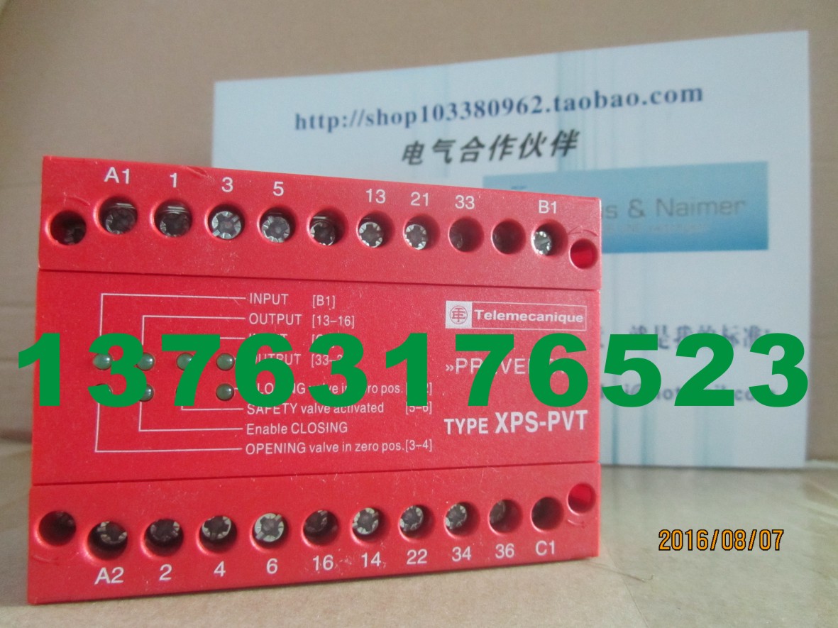
XPSPVT1180
Operating principle Monitor and Processing
Preventa safety module type XPSPVT
For dynamic monitoring of hydraulic valves on
linear presses
Safety module XPSPVT is specifcally designed for monitoring hydraulic safety
system valves which control the movements of potentially dangerous machines.
The operating principle of this module is explained in the circuit diagram
of a hydraulic safety system for linear presses (see below).
This hydraulic safety system features a 3 position piston which controls the up and
down stroke of the operating cylinder. The circuit is equipped with a safety valve
to complete the redundant system. This circuit must be activated to enable the
up and down stroke of the cylinder.
If either of the 2 pistons becomes defective (for example, due to a broken spring
or to oil contamination), and the valve piston shifts from its normal position towards
the open position, the XPSPVT module will detect it and prevent resumption of the
piston stroke.
Proximity sensors integrated in the valve to detect the piston positions and
connected to the XPSPVT module must be damped when the valve coils are in the
de-energised state (zero position).
The sensor circuits of the XPSPVT module are designed to allow connection of NPN
and PNP proximity sensors or sensing components. Either 2-wire or 3-wire types
can be used.
Hydraulic safety system circuit operating on a linear press.
Monitoring of valves in position 0.
(1) 3 position hydraulic valve.
(2) 2 position hydraulic valve.
S3
A B
(2) P Y3
(1)
S2
Y2
S1
Y1
A B
P T
Pressure
release valve
Opening
Pressure
release
Pump valve
Closing +
opening
Closing
|
Description
|
Display
|
Supply
|
Reference
|
Weight
kg/
lb
|
Safety module for
dynamic monitoring of
hydraulic valves on
linear presses
|
8 LEDs
|
24 V c
|
XPSPVT1180
|
0.540/
1.190
|
1 2 3 4 5 6 7 8 9
10
3/91
|
Operating principle
|
Safety module XPSPVK is specially designed for dynamic monitoring of the safety
valves in eccentric presses, conforming to European standard EN 692.
This standard establishes the specifcations related to safety control systems for
presses equipped with friction clutches.
To meet the requirements of this standard, the clutch/brake control must be monitored
dynamically.
This function is provided by a double-bodied solenoid valve (safety valve for presses)
which performs the functions of two valves mounted in one body.
The position of the two valve pistons can be monitored by proximity sensors, mechanical
limit switches or pressure switches.
Module XPSPVK checks for the correct operation of the double-bodied safety valves
at 3 points in the cycle.
b Start at top dead centre: checks the rest position of the two valves.
b Take-on point (transfer function): checks that the two valves are in the “activated”
(energised) position.
b Press stop trigger point: checks that the two valves return to the rest position.
Return must be simultaneous for both valves within a defned time period.
To set up an automatic disconnect of the XPSPVK module at the frst machine stroke,
a NC auxiliary contact mounted on the main control contactor or on another contactor/
relay, activated at the same time, can be wired to terminals 7 and 8 in parallel with the
RESET button.
If a fault is detected during the cycle, the XPSPVK module will stop the slide stroke
and will also inhibit the start of another cycle.
|
Operating principle,
references
Monitor and Processing
Preventa safety modules type XPSPVK
For dynamic monitoring of double-bodied solenoid
valves
XPSPVK
|
Description
|
Display
|
Supply
|
Reference
|
Weight
kg/
lb
|
Safety modules for
dynamic monitoring
of double-bodied
solenoid valves
|
8 LEDs
|
24 V c
|
XPSPVK1184
|
0.700/
1.543
|
|
115 V a
|
XPSPVK3484
|
0.900/
1.984
|
|
230 V a
|
XPSPVK3784
|
0.900/
1.984
|
1 2 3 4 5 6 7 8 9
10
3/92
Operating principle Monitor and Processing
Preventa safety modules type XPSOT
For safety stop with automatic overtravel monitoring
and control
|
Operating principle
|
Safety module XPSOT is used on eccentric presses to monitor overtravel and
ensure that the press slide stops in a non-dangerous position, i.e. top dead centre
(TDC), during normal (non-emergency) operation.
Use of this module, designed in accordance with standard EN 692 relating to
mechanical press safety, makes it possible to create a redundant, self-monitoring
control system.
The two essential functions of this safety module are to:
b Trigger the end of cycle stop sequences slightly before top dead centre
(at point A) so as to come to a complete stop at TDC.
After TDC, the permissible overtravel is approximately 10°. The safety module
immediately detects any overtravel. Overtravel is indicative of braking device
deterioration and, in this case, jog mode must be used to move the slide back
to TDC. The next cycle will be inhibited to allow maintenance to be performed
on the braking device (cam 1).
b Take over control monitoring during the dangerous part of the cycle (slide
downstroke). Any stop instruction issued between TDC (0°) and point C
(approximately 150° after TDC) causes an immediate stop of the press.
This approximate value of 150° corresponds to the 8 mm tool closure
dimension (safety point).
When a stop instruction is issued after this safety point, the press completes the
cycle and comes to a complete stop at TDC (cam 2).
Control of the dangerous part of the cycle (generally the slide downstroke) is
usually activated from a two-hand control station associated with a safety module
(type XPSBCE).
Overtravel monitoring is performed on each cycle by safety module XPSOT.
|
1 2 3 4 5
|